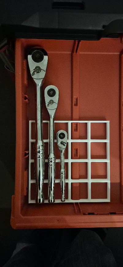
I wanted to organize my toolbox using the Gridfinity system by Zack Freedman, but I wanted inserts that perfectly fit the tools I actually when working on my vehicle. Rather than my traditional approach of measuring everything with digital calipers, I went with something simple: a basic flatbed scanner. The results were great, and the process surprisingly smooth.
🧩Step 0: Will it Fit?
Before I started, I laid out some of the larger tools that I wanted to store to make sure they would actually fit .

🖨️ Step 1: Flatbed Scanning
I arranged the tools I wanted to organize on a cheap flatbed scanner, keeping them flat and spaced. I also put a ruler on the bed so I can accurately scale the image in Fusion360 .
💻 Step 2: Inserting the Scan into Fusion 360
In Fusion 360, I started by creating a model of the tool that I am trying to store. I started a new sketch and imported the scanned image as a canvas. After calibrating the canvas using the ruler, I traced the tool outlines using the spline and line tools. I used the extrude and revolve tools to create a 3d model of the tool. From there, I used the Gridfnity generator plug-in and finally, I subtracted 3d model of the tool from the gridfinity base.
🧱 Step 3: Making It Gridfinity
I used Zack Freedman’s published specs for Gridfinity modules 42mm squares, and the Fusion360 Gridfinity Generator to create a blank, that I could then subtract the tool from.
🖨️ Step 4: 3D Printing the Inserts
I exported the final design as a STEP file because I am printing in multiple colours, I sliced it in BambuSlicer. I used PLA+, PETG would be better, but the PLA+ was already loaded. Everything printed smoothly and (after the 2nd attempt) the fit was excellent.
✅ Final Thoughts
Using a flatbed scanner was a low-cost, low-effort alternative to 3D scanning or caliper modeling. It gave me just enough accuracy to design inserts that really fit my tools—and it worked well with Fusion 360’s canvas workflow. I’ll definitely use this technique again.